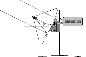
Ignoring practical complications, installation involves setting (all angles in degrees) …
Although calculating values for these settings, which is covered later, involves 3-dimensional geometry that can be hard to visualise, given the right ones, normally they are easily applied. The exception might be elevation, because not all dishes have scales, and because it may have more than one component, though the latter case can be simplified with a scientific rule …
Where a system consists of two rigid structures connected by a pivot, any rotation about the pivot rotates an entire structure on one or other side of it through the same angle.
Further, where there are N rigid structures connected by N−1 parallel pivots, by considering what happens when only one pivot is free to rotate at a time, the rule can be applied successively to each in turn, giving the result that the total angular movement is the sum of the component movements, allowing for the direction of each by assigning its angle a positive or negative sign according to some agreed convention.
As I have not been able to find on the web a citation for this rule to state it more scientifically, hopefully my own name for and manner of expressing it based on memory will be acceptable. Anyway, it can be verified easily by adding construction lines to diagrams and applying school level geometry.
A natural convention is that a rotation raising the incoming beam focused by a dish, clockwise in the following diagrams, will be positive, any lowering it, anticlockwise in the diagrams, will be negative. Also, a mathematical 'rotation' needn't mean something free to turn in reality, for example the offset in an asymmetric dish (a negative rotation of the receiving component's mounting arm which the laws of reflection convert to a positive one for the incoming beam) and the angle of a rotor crank can both be considered 'rotations' made during manufacture.
As a first example, applying the rule to a dish with its mounting as one rigid structure, the dish itself the other, and the elevation mechanism the pivot, it becomes clear that elevating the dish will tilt the line of focus, difficult to measure, through the same angle as the back of the dish, easier. Thus, in the diagram of an axi-symmetric dish below, these two angles can be marked equal as shown.
Dishes focus the incoming electro-magnetic signal by means of a concave reflector, which is aligned vertically by an elevation mechanism. Most, but not all, elevation mechanisms have a scale, the precise meaning of which depends on the type of dish. There are two main types in common use:

Usually there's a scale on the adjuster representing actual elevation, and then …
Actual elevation = elevation setting
… but occasionally there's no scale and one of the two angles shown must be measured.
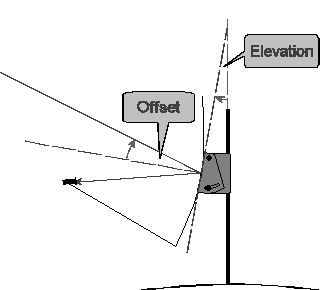
Scales on adjusters usually compensate for offset and read 20-30° when the dish is pointing horizontally, then …
Actual elevation = elevation setting
… but a few have 'true', uncompensated scales that read zero at horizontal, and by the Pivot Rule …
Actual elevation = elevation setting + offset
If there's no scale, both angles must somehow be measured, and …
Actual elevation = dish elevation + offset
See the General Introduction
Preferably offset should come from the dish specifications. Otherwise …
Measure the distances d between points at the top and bottom of the reflecting face of the dish, and dT and dB of these from the focal point, which will be at or a little behind the front face of the LNB. Then …
Offset = asin[ (dT - dB) / d ]
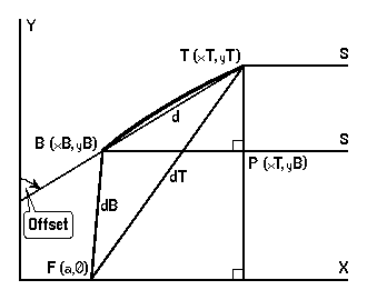
Proof: It is a defining property of the parabola y2 = 4ax that the distance of any point (x,y) on it, from the focus F = (a,0), equals its distance x + a from the directrix x = -a (not shown). An arbitrary offset dish is made by choosing any bottom B and top T on this curve, and the Offset is then the angle the line of the dish TB makes with Y. Rays from a satellite S, effectively parallel to X, hit T and B and are reflected to F …
| PTB | = | Offset | Alternate Angles, TP || Y | |
| ∴ | sin( Offset ) | = | PB / TB | |
| ∴ | sin( Offset ) | = | ( xT - xB ) / d | |
| But | dT | = | xT + a | |
| ∴ | xT | = | dT - a | |
| & | xB | = | dB - a | Similarly |
| ∴ | xT - xB | = | dT - dB | |
| ∴ | sin( Offset ) | = | ( dT - dB ) / d | |
| ∴ | Offset | = | asin[ (dT - dB)/d ] |
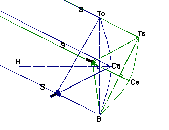
Effectively parallel rays from a satellite S are focused by an offset dish in blue. This being vertical, by definition SCoH is the Offset (and the elevation of this satellite). As the rays make angle Offset with the horizontal, they must make 90 − Offset with any vertical, including ToB. In green the dish has been squashed vertically and tilted back into an axi-symmetric equivalent that intercepts and focuses the same rays. Since BToTs is 90 − Offset, and ToTsB is a right-angled triangle …
| ToBTs = Offset | |
| & | Offset = ArcCos ( TsB / ToB ) |
… but, the squashed dish being round, TsB is the same as its width, and, the dish being squashed only vertically, this is also the width of the offset dish, hence …
Offset = ArcCos ( width / height )
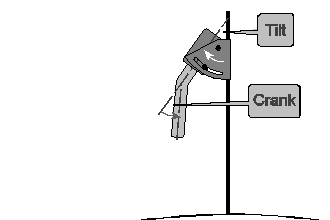
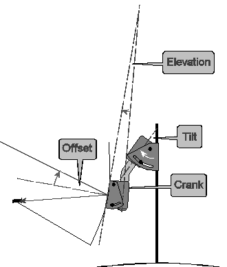
Applying the Pivot Rule first to the rotor alone, the tilt and crank angles are positive and negative respectively.
Applying the rule then to the whole assembly …
Actual elevation = tilt - crank + dish contribution
… if, as normal, the dish has a scale that compensates for the offset …
Actual elevation = tilt - crank + dish setting
… otherwise …
Actual elevation = tilt - crank + elevation + offset
Unfortunately, use of these formulae is hampered by the absence of the crank angle from most rotor specifications, a sloppy omission. However, the angle may often be deduced indirectly from the dish elevation formula:
Some manufacturers give a formula like …
Dish elevation = x - declination
… where x is actually the crank angle and declination is read from a table. So, for example, the PowerTech DG-240 has a crank angle of 35°.
Some give a formula which can be used in combination with the above formulae to work out the crank angle.
For example, STAB's dish elevation formula for their HH1x0 Rotors is …
Setting on rotor = setting off rotor - (60 - latitude)
… so, as the settings on and off the rotor must both result in the actual elevation, and the tilt measured from vertical will normally be 90 - latitude, on these models the crank angle is 30° …
| Actual elevation | = | tilt - crank + dish setting | ||
| ∴ | Actual elevation | = | 90 - latitude - crank + actual elevation - (60 - latitude) | |
| ∴ | Actual elevation | = | 90 - latitude - crank + actual elevation - 60 + latitude | |
| ∴ | Crank | = | 90 - 60 | |
| ∴ | Crank | = | 30 |